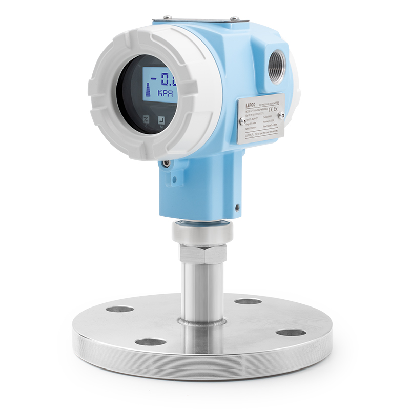
LFT705 Flange Pressure Transmitter
High-precision pressure measurement with digital display and data logging capabilities for industrial applications.
Product Brochure
Download detailed specifications
LFT705 Flange Pressure Transmitter
Product features
-
■Flange connection,compatible with industrial pipeline connections
■Utilizes MEMS single-crystal silicon high-precision pressure sensor
■High stability with a measurement accuracy of 0.2%FS
■Multiple diaphragm materials available to suit various media
■Equipped with a backlit high-brightness LCD display,display can be inverted
■On-site zeroing function,on-site zero and span adjustment and calibration capabilities
■Three output options:RS485,4~20mA,and 4~20mA+HART
Detailed Description
OVERVIEW
LFT705 can accurately measure the pressure of liquid,gas or steamand convert it into a 4~20mA output signal.It can be operated bythree buttons on the Transmitteror through Hand Manipulator orConfiguration Software.The display and configuration adjustmentcan be performed without impacting 4~20mA output signal.It iswidely used in pressure measurements in industrial sites such aspetroleum,chemical,electric power,and hydrology.
STANDARD SPECIFICATIONS
Pressure range is calibrated based on the standard zero point,stainless steel 316L diaphragm,illed liquid is silicone oil.
PERFORMANCE REQUIREMEN
Overal performance includes but not limited to referenceaccuracy,static pressure influence,ambient temperatureinfluence,and other influence.
1)Pressure calibration reference accuracy | ||||
Including linearity,hysteresis and repeatability from zero point | ||||
Linear output | Td≤10 | ±0.2% | Standard range: | |
10<TD≤100 | ±0.02TD% | |||
TD is range turn down ratio. |
| |||
2)Power supply influence
When the power supply voltage varies within 12~36 VDC,if zero point and span variation not exceed±0.005%*URV per voltage,the influence can be ignored.
FUNCTIONAL SPECIFICATION
1)Range selection
Within the upper lower limit(URL)and lower range limit(LRL),you can adjust the TD value within the allowable ange toselect the range.For example,if URL and LRL-40-40kPa,then adjust the TD value to 10 and select the output of 0-4kPaor-4-4kPa.To ensure accuracy,the TD value should be assmallas possible,generally within 10.
2)Zero point setting
Zero and Span can be adjusted to any value within themeasuring range in the table,as long as calibrated span≥minimum span.
3)Impact of the installation position
Installation at any position,if offset pressure not more than400Pa,can be corrected by zero clearing.
4)Range | |||
Gauge pressure | |||
Range/Upper and lower | kPa | Range ratio TD | |
C | Range | 1~40 | 1~40 |
URL&LRL | -40~40 | ||
D | Range | 2.5~250 | 1~100 |
URL&LRL | -100~250 | ||
E | Range | 10~1000 | 1~100 |
URL&LRL | -100~1000 | ||
F | Range | 30~3000 | 1~100 |
URL&LRL | -100~3000 | ||
G | Range | 100~10000 | 1~100 |
URL&LRL | -100~10000 | ||
5)Output | ||
Signal | Type | Output method |
4~20mA | linear | two-wire |
4~20mA+HART | linear | two-wire |
RS485 | linear | four-wire |
6)Alarm current
Low alarm mode(minimum):3.8mAHigh alarm mode(maximum):20.8mA
No alarm mode(hold):maintain the effective currentvalue before the faultAlarm current standard setting:high alarm mode
7)Response time
Total damping constant time:equal to the sum of thedampingtime constants of the electronic circuit componentsand the sensor diaphragm box;Damping time of electronic circuit components:adjustable from 0-60 seconds;Sensor diaphragm box damping time:s0.2 seconds;Power-on starf-up time after power failure:≤5seconds;
Data recovery time to normal use:s2 seconds;
8)Environmental temperature | |
ltem | Spec |
Ambient working temperature | -20~70℃with display |
Storage temperature | -40~85℃ |
Operating ambient humidity | 5-100%RH@40℃ |
Protection | IP65 |
Dangerous occasions | ExdllCT6 |
Related Products
Ultrasonic Flow Meter
Non-invasive flow measurement for liquids and gases with high accuracy.
Capacitive Level Sensor
Continuous level measurement for liquids and solids in industrial applications.
Temperature Transmitter
Precision temperature measurement with 4-20mA output for industrial control systems.
Portable pH Meter
Accurate pH measurement for water treatment, food processing, and laboratory applications.